 Client Login
WAS-3000 Acoustic Modulator Source: Simplicity, Adaptability, Unsurpassed Precision
Originally developed under the Wyle name, our Huntsville, AL location offers the WAS 3000 acoustic modulator. The WAS-3000 acoustic modulator source is an electro-pneumatic noise source rated at 40 kW output over a frequency range of 25 to 10,000 Hz. Primarily used in acoustic test chambers, the WAS 3000 provides the full range of noise evaluation of large components for spacecraft, missile, and advanced aircraft systems.
The WAS 3000 with internally mounted MU-110 modulation voice coil uses the principle of vibrating vanes to reproduce exact sine wave, random noise and sine-random combinations. In larger chambers, the units can generate overall sound pressure levels up to 165 dB. Higher sound pressure levels can be attained in very small volume enclosures, or by using multiple modulators.
Sure Flights and Launches Begin with the WAS-3000 Simulation Testing Application
Pre-flight qualification testing of structures and components provides added assurance of meeting the high reliability requirements of aerospace vehicles. Vibration during launch and flight operations is a major concern. Since pressure fluctuation over the external skin is the principal source of vibration in modern flight vehicles, acoustic energy offers a logical and effective simulation tool for reliability testing.
Acoustic test facilities which simulate these external pressure fluctuations can be used for structural and component testing. Qualification tests can be designed to evaluate designs, to gauge reliability and to provide total system checkout.
The Advantages of Simple, Reliable Operation
The advantages of the WAS-3000’s vibrating vane modulator include:
- A true random noise input produces a true random noise output.
- Additional signals, such as discrete frequencies or sweeps, can be superimposed on the random noise.
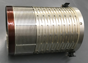
The WAS 3000 uses airstream modulation to product pressure fluctuations associated with high-intensity sound. The MU-110 voice coil incorporates two concentric cylinders, each having rows of modulation slots. These cylinders form the stator and armature of the voice coil. Slots are cut around the periphery of the armature so that axial motion of the armature against the suspension varies the openings formed by the two sets of slots that are in both armature and stator. With air pressure applied outside of the armature, air if forced through these slots. The stator is mounted inside of the armature and has no spring slots. The stator and armature are assembled such that the beams between the armature modulation slots cover one half of each slot in the stator.
Motion in the voice coil increases and decreases the opening size of the modulation slots based on the polarity of the electrical input signal. This process breaks the airstream into “puffs” which become the pressure pulses at the discharge of the WAS 3000.
General Characteristics of the WAS-3000
The WAS 3000 with the MU-110 modulation voice coil is simple and reliable and converts approximately 3000 scfm (85 m3/min) at 30 psig (2 bar) of airflow into 25,000 to 30,000 acoustic watts. The relationship of air flow to power output is linear.
The MU-110 armature is the only moving part in the WAS 3000 system and all critical alignment between the armature and the stator elements is performed at the factory and, as a result, no field adjustments are required.
The WAS 3000 uses a ALNICO V permanent magnet with the MU-110 voice coil and requires only compressed air and electrical drive signal for operation. The WAS 3000 operates at any altitude and is easily moved and installed from one location to another.
WAS 3000 Specifications
Maximum Acoustical Power Output: 30,000 Watts
Frequency Range (Input): 0 – 630 Hz
Frequency Range (Output): 25 – 10,000 Hz
Airflow Rate (Nominal): 3,000 scfm (85m3/Min), 3.8 Lbs/Sec. (1.7 Kg/Sec.)
Air Supply Pressure (Nominal): 28 Psig (1.9 Bar)
Air Supply Pressure: 40 Psig (2.7 Bar), 10 Psig (.7 Bar)
Air Supply Filtration: 80 Microns
Air Supply Temperature: -70 To +100F (-39 To 55C)
Overall Length With Pneumatic Coupler: 28 1/32 In. (71.2 Cm)
Length Without Pneumatic Coupler: 24 9/32 In (61.7 Cm)
Pneumatic Coupler (Quick Disconnect): 4 In. Kamlok
Diameter: 12 11/16 in. (32.2 cm.)
Horn Connection: 8 ea. 3/8 in. bolts
Horn Flange Thickness (Not Supplied): 1 in. (2.5 cm.)
Output Throat Diameter: 4.0 in. (10.2 cm.)
Mounting Attitude: Optional
Weight: 185 lbs. (84 kg.)
Electrical Input Connector: MS 3102R165-8P
MU-110 Modulation Voice Coil Specifications
Electrical drive power 600 VA maximum
Normal drive current 8 – 11 amps
Coil resistance 1.75 nominal
Normal drive voltage 20 – 40 volts
Normal input impedance 2 – 4 ohms
Full Service Support Designed to Save You Time and Money
Since 1949, GVIRL has been a specialized testing and simulation services partner to the Aerospace, Defense, and Commercial industries.
We save you precious time, # and money for short-term test requirements through GVIRL-owned and operated reverberant and progressive wave acoustic test facilities.
We’ll streamline the big picture, too, by supplying turnkey acoustic facility development and engineering support. GVIRL is fully capable of taking on single-source responsibility for design, engineering, construction management, instrumentation and control systems, operation, maintenance, and personnel training.
To request a quote or discuss your needs, please contact us today!